Measure
Set up and measuring procedure
- Select "Measure"
 in Workflow.
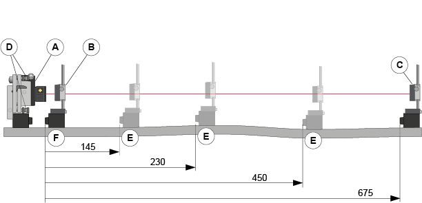
 - Place the laser transmitter [A] on the object to be measured.
- Place the detector [B] as close as possible to the laser transmitter.
- Adjust the laser transmitter horizontally and the detector vertically on the rods, until the laser hits the center of the detector PSD (close to 0.00).
- Select
 to zero set the value (see "Halve or zero set value for a specific detector live reading" below). This is now set up point number one (mark the set up point on the object to be measured).
 - Move the detector to point [C], the farthest point to be measured.
- Aim the laser beam, by using the laser adjustment screws [D], to hit the center of the detector PSD (close to 0.00). This is now set up point number two.
- Repeat step 5-7 and fine adjust the set up points.
- Register measurement values on selected distances [E], see "Measure" below. Distances are always measured from the first point [F]. Do not touch the laser transmitter.
- Choose reference points, for example first and last measurement points.
NOTE! The more accurate you are when setting the laser beam parallel to the object to be measured, the more accurate the measurement result will be.
Measure
- Tap "Measure”
 in the workflow, see Measure view below.
 - Tap
 to register values.
 - To remeasure, select a registered measurement point in the list and tap , see Measure view below.
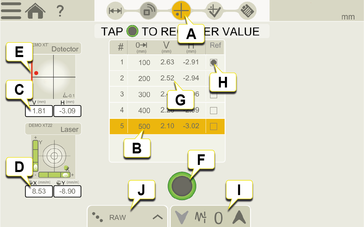
Measure view.
- Measure icon is active in the workflow.
- Measurement position.
- Live reading of detector.
- Live reading of laser transmitter.
-
Edge warning. When the laser beam is close to the edge, the edge is “lit up” as a warning. It is still possible to register values when the edge warning is active, but the measurement accuracy may be reduced.
-
Tap to register measurement value for active measurement position.
- Registered measurement values.
-
Reference point. To select reference point, first tap "Reference" in Reference modes.
-
Tap to select filter for detector. Go to Filter
-
Reference modes.
Measure with reference detector
When measuring, you can check the value from the reference detector by pressing the Device button. It is only possible to monitor the values from the reference sensor.
-
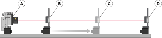
Laser transmitter.
- M unit detector.
-
M unit detector at farthest point to be measured.
-
S unit used as reference detector during Measuring-procedure, placed beyond farthest point to be measured.
Zero set value when live device is zoomed in (remove M unit detector [C] when checking the reference detector).
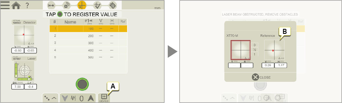
- Tap to display Reference detector Live Device.
- Zero set and halve the value when Live Device is displayed.
This does not affect the measurement.
An XT70-S can be used as reference detector. To set it to Reference mode, see below. When set to Reference mode the XT70-S display will show an "R". Other detectors that can be used as reference detectors are XT70-M and XT9. These detectors will not show an "R" when set to reference mode.

Display showing an "R" when XT70-S is set to Reference mode.
NOTE! The XT70-S unit will behave as an M unit when "Reference mode" is selected in the app, meaning M values are shown in the display.This is indicated by an "R". The XT70-S unit is automatically set to "Reference mode" during the entire measurement session. The XT70-S will go back to "normal mode" when disconnected from the app.
NOTE! "Reference mode" will automatically be switched off when you change program, for example to "Shaft".
Tolerance
By default, no tolerance is set. To set tolerance, add preferred values.
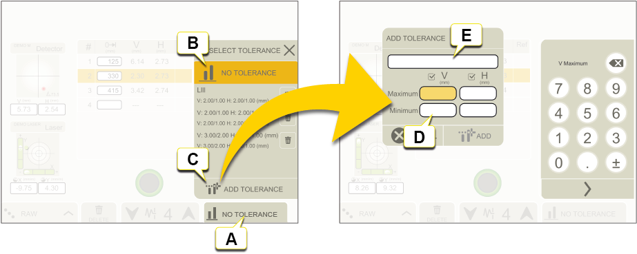
- Tap to set tolerances.
- No tolerance (default).
- Add tolerance.
- Set tolerances for vertical and horizontal offset on the keyboard.
- If you like to give the tolerance a specific name, write it here.
Reference modes
When you perform a best fit calculation, the object is tilted to the lowest peak to peak value. It is fitted as straight as possible between two planes.

|
Raw values. |

|
Zero. When you perform a best fit calculation, the measurement object is tilted to the lowest peak to peak value. It is fitted as flat as possible between two planes where the average value is zero. |

|
Negative. Best fit with all measurement points below 0. The reference line is moved to the highest measurement point. |

|
Positive. Best fit with all measurement points above 0. The reference line is moved to the lowest measurement point. |

|
Average. The reference line is moved to the average value of the measurement points. |

|
Set custom reference point. |
Halve or zero set value for the detector live reading
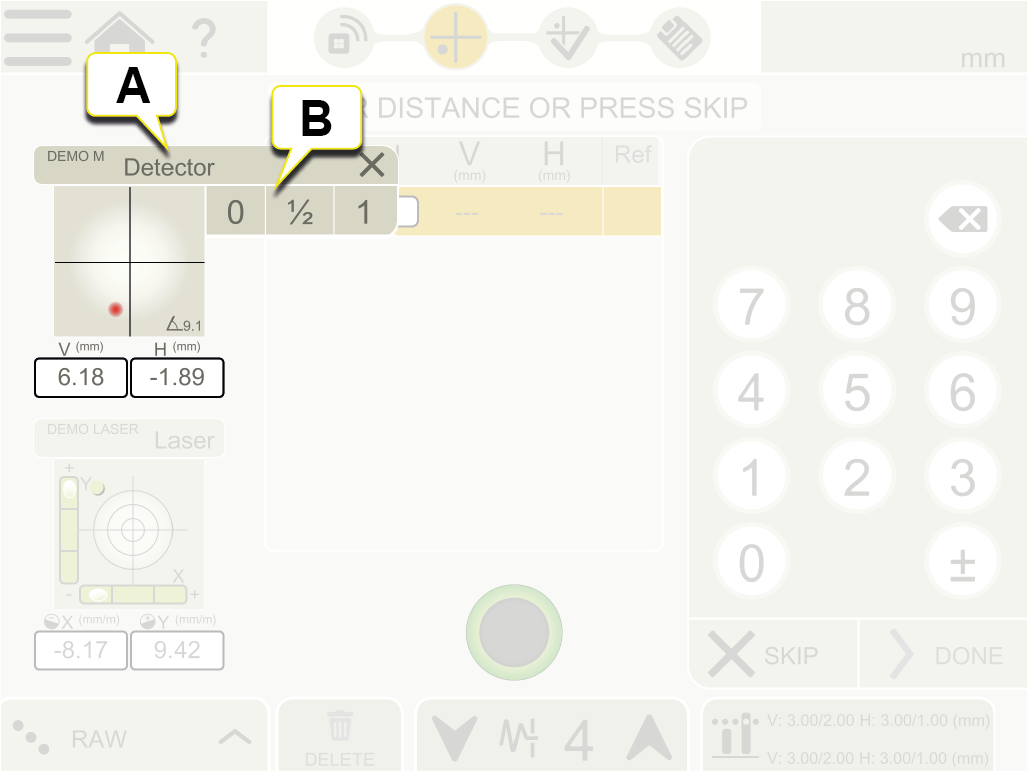
- Tap the Live Device View to open Context menu.
- Tap "0" to zero set, "1/2" to halve value or "1" to return to the absolute value.
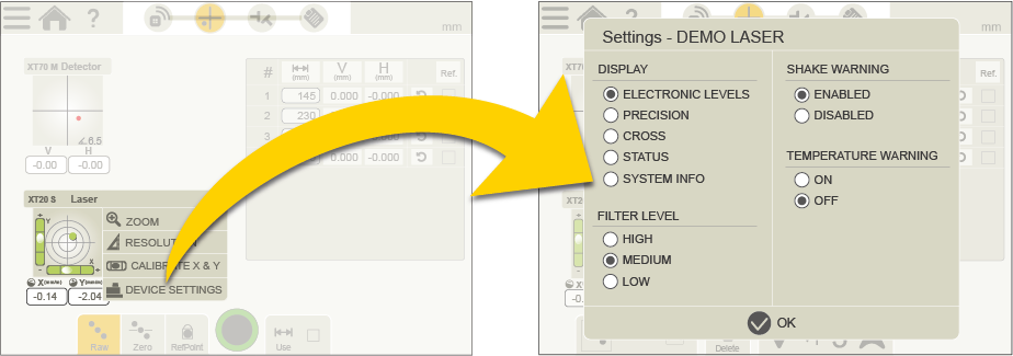
Device settings for XT20 and XT22
Tap the Live Device View to open Context menu and tap "DEVICE SETTINGS". Set Display view, Filter level and activation/deactivation of Shake warning and Temperature warning.
Warnings during measurement
The following Warnings may appear in the Live Device information:
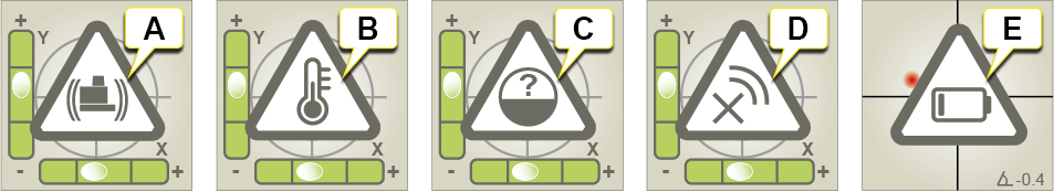
- Shake warning for laser transmitter. Deactivate by selecting Shake warning "OFF" in the XT app. If vibrations are strong enough to make the shake warning appear during measurement, increase the filter level of electronic levels from the XT app.
- Temperature warning for laser transmitter. Deactivate by selecting Temperature warning "OFF" in the XT app.
- No angular information is available. The electronic levels and inclinometers of the laser transmitter are out of range. Please position the transmitter closer to horizontal or vertical level.
- Device disconnected.
- Low battery warning. Charge the measuring device.