Easy-Laser has for many years been one of the leading suppliers of measurement and alignment systems for the wind power industry, both for shaft/coupling alignment and flatness measurement of tower flanges. Our customers are some of the world's largest manufacturers of wind turbines, such as Vestas, Siemens/Gamesa, Envision, Goldwind amongst others. Here are some examples of what we offer.
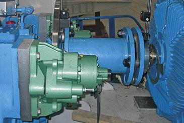
Standard shaft alignment systems or specially adapted OEM variants are used here. The latter are designed to fit a turbine manufacturer's specific dimensions of the couplings on a large number of turbine variants in their range. They are designed to be used with the coupling removed and the rotor locked, as this is the safest for the operator.
Easy-Laser's standard system is used on other coupling designs and where it is considered safe to leave the coupling in place. They are intended both for installation and for continuous maintenance work in the field, and are therefore well suited to the requirements of service companies.
Learn more about our shaft alignment systems for wind turbines.
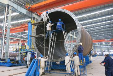
If flatness measurement of the flanges is difficult depends, among other things, on the diameter of the tower. Smaller diameters (up to 4 meters) are usually straightforward to measure. But large diameters, especially large offshore towers, require a different approach.
Our patented sectional measurement software is ideal to use in this case. With this method, the flange is measured as four sections, which are then mathematically combined for a complete result. There are two main advantages to this: the measurement is not affected by the flange being deformed by its own weight (gravitational impact). It also makes the work safer for the technician, who does not have to stand on a high ladder or platform – all measurement takes place from ground level. See more in this video.
You can measure up to 5 circles with measuring points per flange, and check not only the flatness but also the angle ("taper") of the flange relative to the flange plane for correct joining of the tower sections. Immediately after completing the measurement, you can view the result as a 3D image in the display unit and evaluate the results with different best-fit calculations for possible further processing. This can be done directly on site, without having to use a PC with a separate analysis programs, which streamlines the work.
The flanges on the blade and the blade attachment to the hub should also be flat. This is checked using same type of measurement equipment as for tower flanges.

