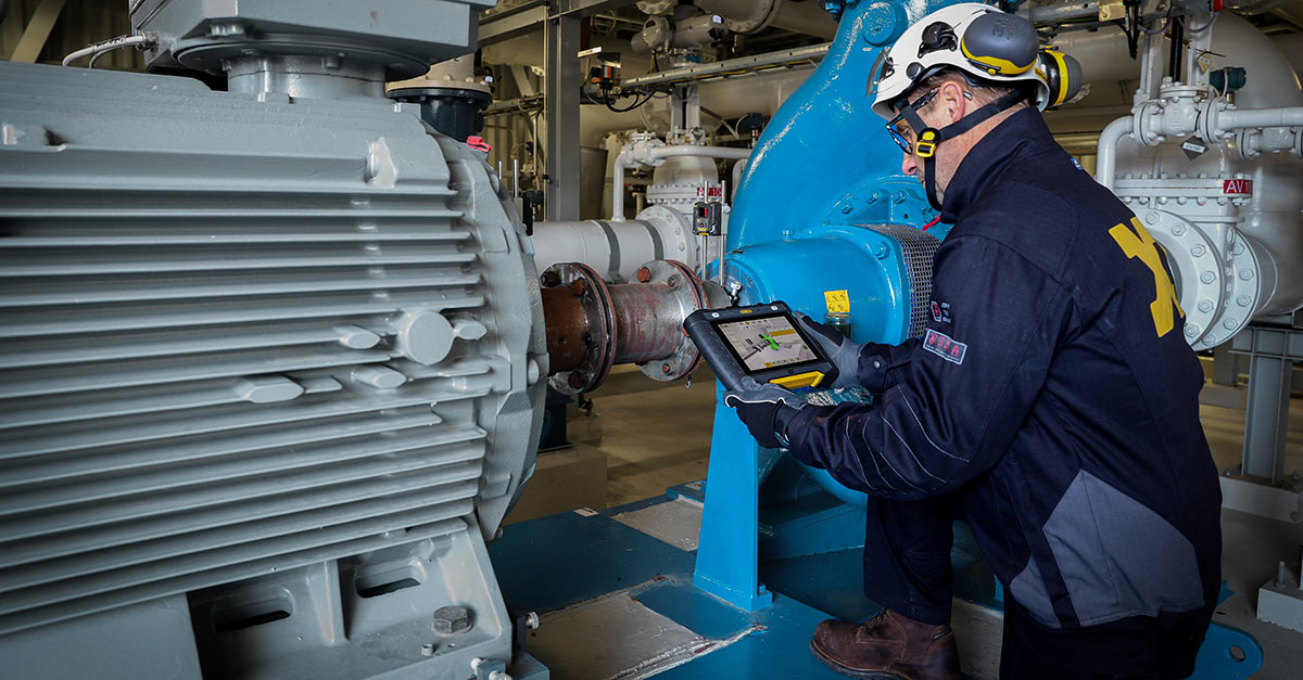
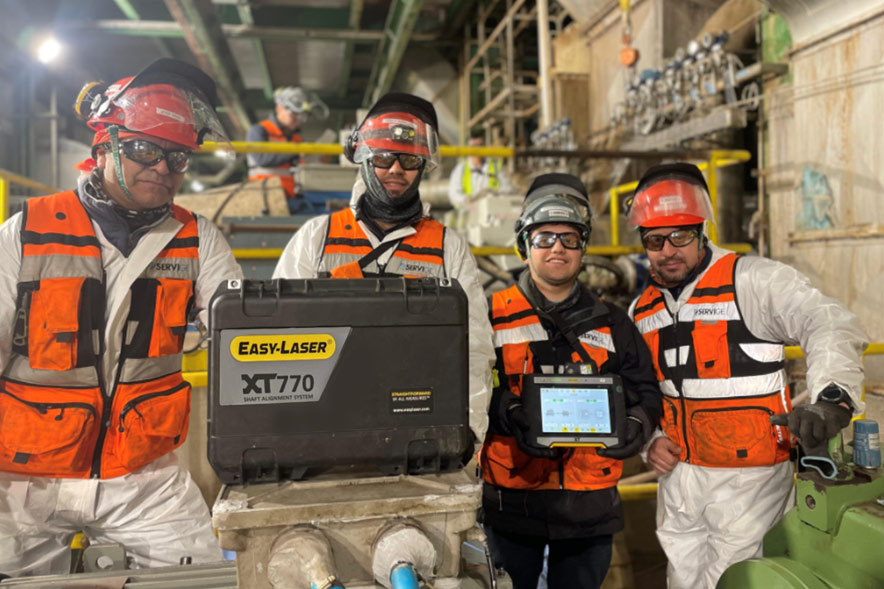
Today, laser alignment systems make the job faster and more accurate, and they can adapt to a wide range of machine setups. In this article we’ll take a closer look at how the Easy-Laser alignment systems handle different machine configurations: horizontal, vertical, cardan/offset mounted, and machine trains.
1. Horizontal machine alignment
The most common alignment scenario involves two horizontally mounted machines, typically an electric motor driving a pump, fan, or gearbox. Laser systems are ideal for this setup. With a laser measuring unit mounted on each shaft, the system calculates shaft centerlines in real time, even while adjustments are made. The digital readout shows horizontal and vertical alignment values simultaneously, guiding the user through corrections with live feedback. This significantly reduces the time needed compared to traditional methods and ensures consistently high precision.
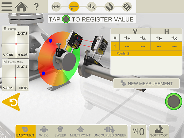 The Horizontal measurement program in the XT Alignment app offers five different measurement methods: EasyTurn, 9-12-3, Sweep, Multi point and Uncoupled sweep.
2. Vertical machine alignment
The vertical configuration is most common in pump applications, where the motor is mounted on top of the pump, often with a flange connection.
Vertical or flange-mounted motors present a different geometry, where the shaft rotates along a vertical axis. Alignment challenges often involve angular misalignment due to uneven flange contact or distorted mounting surfaces. The Easy-Laser systems include a dedicated vertical alignment program. It calculates center offset and angular deviation at multiple clock positions and provides adjustment values based on shims or repositioning. The result: fast and accurate alignment even when access is limited.
 The Vertical measurement program in the XT Alignment app offers step-by-step guidance.
3. Cardan or offset mounted machine alignment
Some machines are connected via cardan shafts. These setups require the driver and driven shafts to be parallel, not colinear, making traditional alignment methods difficult. The laser system solves this by using a cardan shaft program that allows the user to align the motor based on angular and offset tolerances at defined measurement planes. With the cardan shaft temporarily removed, the laser measurement units are mounted on special cardan brackets and used to measure shaft positions. The system then provides adjustment values that ensure parallelism, accounting for angular twist and axial offset.
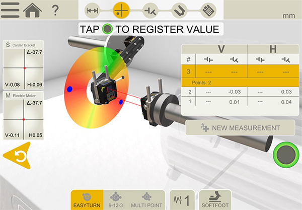 When measuring cardan shaft alignment, the cardan shaft itself is removed and instead a special bracket is used to ensure correct measurement results.
4. Machine train alignment
In multi-machine setups – such as a turbine driving a gearbox and generator, or a motor driving a pump and a compressor – proper alignment across all coupled machines is essential to prevent stress buildup and premature wear. Laser alignment systems simplify this complex task by allowing the user to build a virtual train model in the software. Each machine can be defined as fixed or movable, and the system calculates optimal alignment targets accordingly. Live adjustments can then be made at one or more positions, with results updated across the entire train in real time.
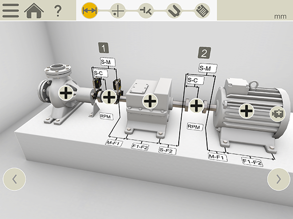
Most Easy-Laser shaft alignment systems come with the machine train measurement program as standard. Using the Easy-Laser XT770 system you can even add an infinite number of machines.
One tool, all configurations
By providing precise measurements, real-time feedback, and dedicated software functions for different configurations, the Easy-Laser systems streamline the alignment process and improve machine performance. Whether you’re maintaining a standalone pump and motor setup or a high-speed production line, investing in accurate alignment tools is always worth it.


