It is important to have, and follow, a standardized process for the installation. A “reliable machinery installation procedure” if you will. You will have to take care of (measure and confirm) things such as foundation flatness/level, pipe fitting, soft foot, machinery (shaft) alignment etc. In this article I will focus on the specific part of pipe strain and its effects on machinery alignment.
Look to the whole machine
Let’s assume that the foundation has been checked for flatness (or never assume, of course check the documentation first), pipe flanges have been lined up, and the machinery has been dropped down ready for initial alignment. If done by the book your next step would be to move forward with the machinery alignment process. You may wonder why I keep writing machinery alignment instead of shaft alignment? Although the end goal is to line up the rotational centre of the shafts you are actually aligning the whole machinery before you even get to the point of precision alignment.
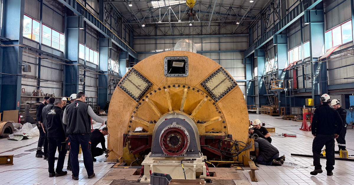
Using the term shaft alignment implies that that is where the focus should be and encourages the mechanics to go straight for precision aligning said shafts. If you do not take care of the whole machine during the installation, you are going to introduce stress into it. With stress I mean applied forces that can cause for example bearing failure, overheating or abnormal power consumption. John Lambert, of Benchmark PDM in Toronto Canada, dubbed it “Stress - the silent killer”. With that he meant that stress in the machinery casing will eventually “kill” your asset.
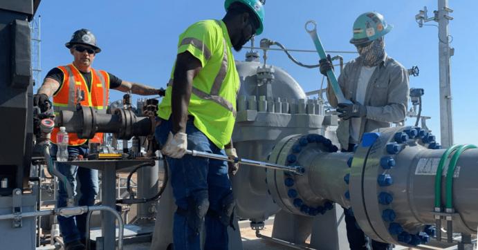
Pump/motor alignment in the field
Let’s take a look at a real-life case. Brian Franks of JetTech Mechanical LLC based out of Goodyear, AZ, was commissioned to install a 3250 hp induction motor (Toshiba) driving an SPX ClydeUnion pump in a natural gas liquids pipeline project stretching from Colorado to Northern Texas.
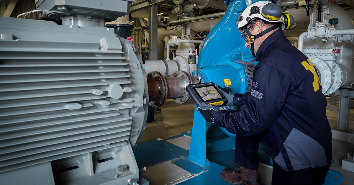
 Laser shaft alignment system mounted using magnetic axial brackets.
Checking for soft foot before initial alignment
The coupling is a 12-inch (304.8 mm) spacer. The first thing you need to do is check for soft foot. Soft foot is a term that is used rather carelessly in the industry as it implies that something is going on with the machine feet. This could of course be true, but often there is something else causing this, such as the base being out of flat, or pipe stress. I am not going to delve deeper into this topic as there are many good articles out there already.
In this example JetTech has loosened (opened) the coupling as well as disconnected the pipes. This is the correct way of performing the initial soft foot check as this will allow you to pinpoint any soft foot issues without seeing any influence from coupling or pipe strain. The base should at this point have been checked for flat and level (before the pump and motor are mounted) ruling out any soft foot caused by the frame being twisted.
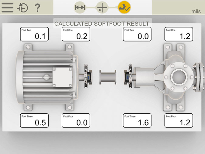 Calculated soft foot results from measurement with a laser shaft alignment system. Numbers in mils (1/1000 of an inch).
Soft foot is measured on both pump and motor. It is not uncommon to focus only on the motor side. An argument we often hear, not to check soft foot on the pump, is that it is stationary and will not be moved (aligned) anyway. Consider the cost replacing the equipment. If you must replace a motor, we are speaking hours. Replacing a pump is a much more complex process that could go on for days. Even if you won’t be moving the pump, you still want to make sure you do not have a soft foot condition as this would distort the casing, and thus induce stress in the pump. Remember, stress is the silent killer.
According to ANSI/ASA S2.75-2017 (Shaft Alignment Methodology, Part 1) allowable tolerances for soft foot is two thousandths (0.05 mm). In this example we are staying below that, at 1.6 mils (0.04 mm) at foot three of the pump. Once soft foot condition has been ruled out, and documented, the team proceeds with initial shaft alignment check.
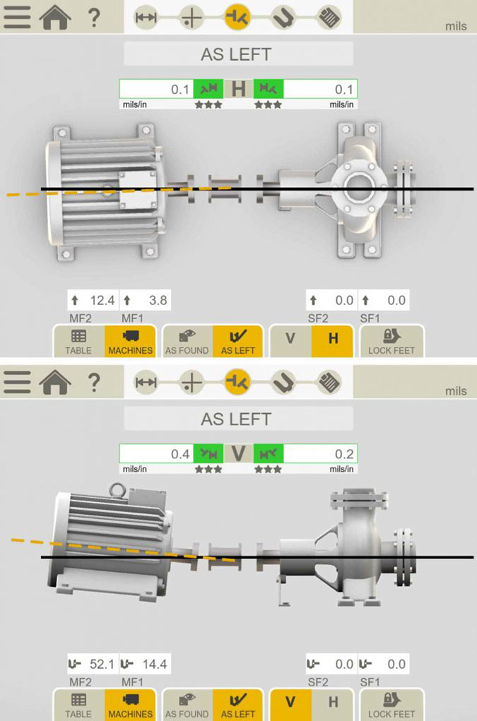 Results from initial shaft alignment check.
As a spacer coupling allows for two points of flexure, tolerances (measurements) are expressed as two angles. In the picture above, the left side shows the horizontal alignment, and the right side shows the vertical. The current setup runs at 3575 rpm. This is important why? The speed of the rotation sets the tolerances for the alignment. At 3575 rpm and spacer coupling the tolerances for shaft alignment are:
| Offset | Angle |
| N/A | 1 mil/ft (0,06 mm/m) |
Shaft alignment tolerance as per ANSI/ASA S2.75-2017
Both horizontal and vertical angles are well within tolerance (thus the green colour in the result pictures). However, remember that we left the coupling and pipe flanges unbolted? The true test of an installation (besides starting it up of course) will be in bolting up the pipe flanges. This should be done under strict supervision (measurement) and should be documented and handed over to the asset owner as proof of a job well done afterwards.
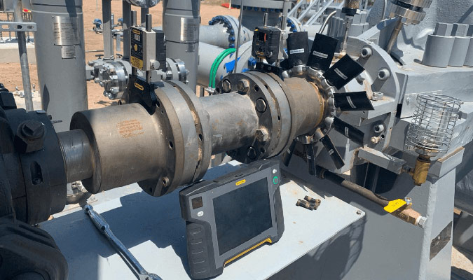
In this case the crew left the laser shaft alignment system mounted on the coupling as they proceeded to torque the bolts.
Identify and eliminate pipe strain
The alignment system has a feature to monitor movement and graph it, in horizontal and vertical direction, as the flange bolts are being tightened. This allows the crew to determine if there is any pipe strain affecting the pump, ultimately adding stress to the machines.
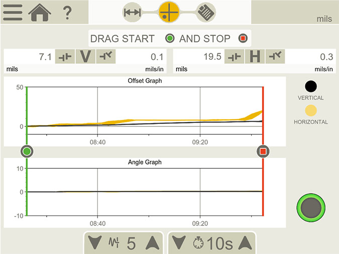 Graph illustrating movement both vertically and horizontally as the pipe flange bolts are tightened.
As you can see in the picture above, there is quite a lot of movement both vertically and horizontally with 7.1 mils (1.8 mm) in vertical offset and 19.5 mils (4.9 mm) in horizontal offset. Going back to the ANSI/ASA S2.75-2017 standard:
“External forces from piping strain, flange strain, conduit strain, attached ductwork, etc., applied to machine cases shall not be sufficient to cause changes in the shaft alignment of magnitude greater than 50 micrometers (2 mils) vertical or horizontal measured at the coupling.”
If the crew would have proceeded with final alignment under these circumstances, they would have seen all kinds of issues, likely manifesting themselves as soft foot. However, this is not a condition you could have fixed using the soft foot playbook (step shims etc). The pipe stress would have been there, adding distortion to your pump case, possibly shaft deflection, causing vibration and ultimately you would see bearing damage because of this.
If you want to make sure your assets run for their entire designed life span, you make sure to take out pipe strain before proceeding to final precision alignment during the installation process.
Mikael Terner, Easy-Laser AB
John Lambert, Benchmark PDM
This article was originally published in Oil & Gas Innovation magazine.