A large, well-renowned construction company had won a contract to build a gate for water level control in a hydropower plant project. The dam was placed upstream from a hydropower station. The two gates (or valves) were approximately 8.5×5 m. Each valve was specified to allow a leakage of 0.2 liters/minute in the closed position. This meant a very tight seal and a requirement of high-precision alignment on the hinges.
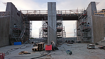
The gate opening.
Traditionally, the construction company had been using a total station on a job like this, using it to determine the geometry of the whole construction. There was a problem, though; they could not use the total station for the gate hinge alignment. We were contracted to do the alignment measurement and also to provide training on the alignment system for the construction workers.
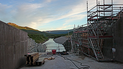
Weather conditions were perfect.
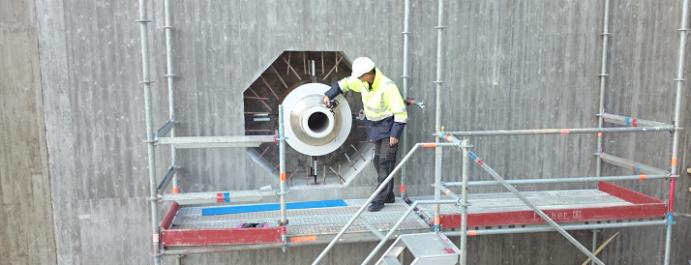
Upon arrival, we found two shaft ends pointing at each other. To allow for a good seal, these two ends had to be aligned with high precision as the sealing surface is within 10 mm on the sides and 20 mm on the bottom of the gate. To solve this alignment, we had to think of the alignment of these shaft ends as an uncoupled, horizontal shaft alignment.
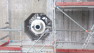
Shaft end (hinge).
We started off with a rough alignment. Using the dual laser coning technique to find the rotational center saved us a lot of time.
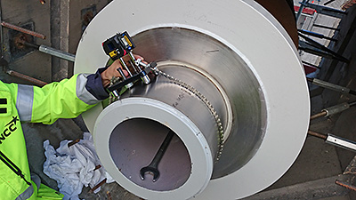
A sliding bracket was used as the shaft end was non-rotatable.
In order to pick which shaft end to designate as the stationary one, we used the E290 digital precision level to check which one was closest to level.
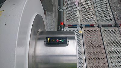 E290 digital precision level.
The shaft ends were checked for parallelism against the sealing surface using the measuring units in the shaft alignment system, and checking straightness over six meters.
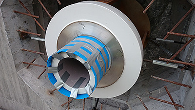
The square marks on the shaft surface are used to pinpoint the position of the mag blocks used for the straightness measurement.
Once the shafts had been measured and adjusted, the construction crew poured concrete around the shafts to lock them into position. After allowing everything to set for two weeks, the gates were mounted without a hinge (pun intended).
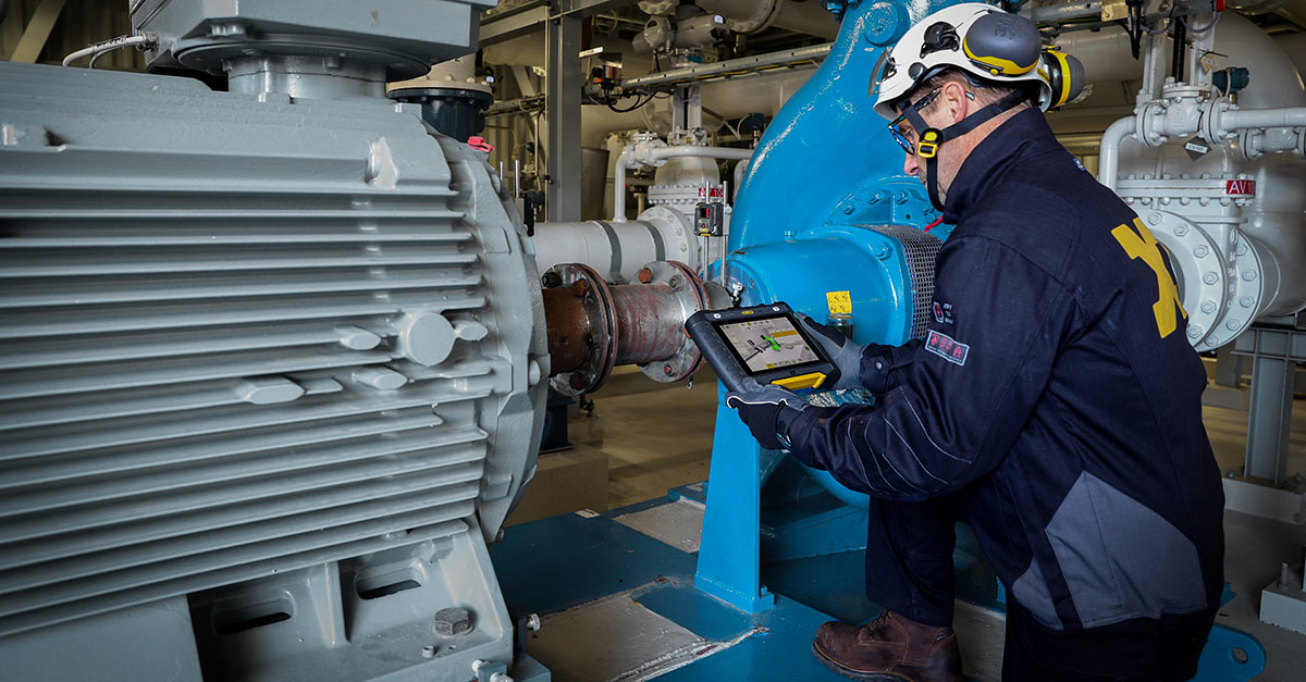
A special point of pride for us here at Easy-Laser is that all these measurements were done with a standard dot laser shaft alignment system combined with a digital precision level. Keep in mind that a digital precision level, such as the XT290, comes in handy in all types of on-site installation work. With it, you can make sure the foundation is flat to within 0.1 mm/m, as specified by most manufacturers.
It is my hope that this application example will inspire you to think in new ways when it comes to alignment. What you perceive as difficult and complicated may in fact, using the right tool, be very easy to do!
Jan Oscander
Measurement technician and Sales engineer

