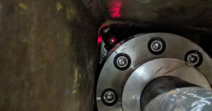
The coupling is round but the hole in the beam was square, just big enough for the coupling to go through. With a circle going through a square, only the corners of the hole were open. This meant that line-of-sight between the two lasers was limited. Because of the obstruction there was no way to obtain data with a continuous reading. Using our dual-laser XT660 system, we decided to take readings in each available corner. We could have taken one point at each 45-degree position. However, taking more points is always beneficial. We decided to take three points (close together) in each of the corners. With two rotations, we obtained excellent repeatability. Once we had repeatable readings, we moved the machine according to the calculated alignment results and aligned it to our customer’s customized tolerances.
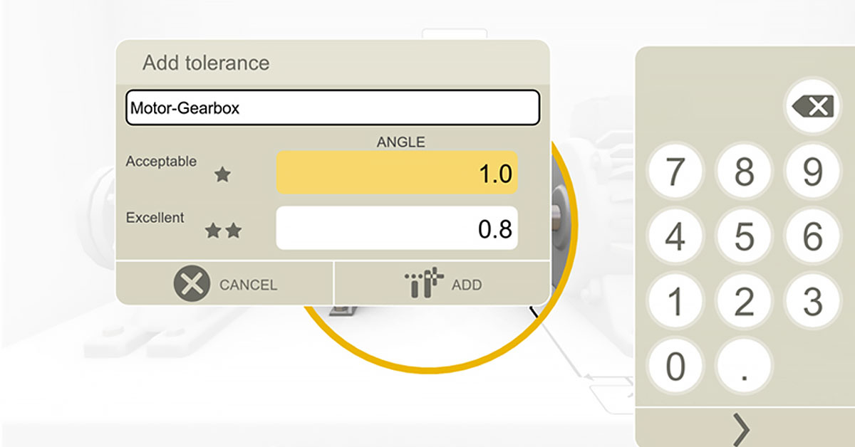
Easy to set custom tolerances
Many times, we are faced with awkward alignment situations. It is helpful to have an alignment tool that is very easy to use, yet versatile to adapt to these situations. It helped that the Easy-Laser® XT660 allowed us to change measurement modes (in this case to Multipoint mode). It also helped that the tool allowed us to adjust our tolerances to the customer’s particular needs. The customer did not want to use the built-in Easy-Laser tolerances, nor the ANSI standard tolerances that are included in the system. Instead, they were looking to align the machines to within 0.1 thou/inch [0.1 mm/m] (or 1.0 thou/10 inches) of angular misalignment at each flex plane. So we created a custom tolerance instantaneously within the tool for this job. The customer was satisfied with the alignment and the report generated with their tolerances.

Adam Stredel CRL
Ludeca, Inc.
This article was originally posted on Ludeca’s blog.


